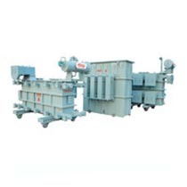

Variable Voltage Regulator Exporter, Supplier and Manufacturer in Gujarat
Power Engineers Company stands as a renowned and reliable manufacturer, supplier, and exporter of variable voltage regulators in Gujarat. Our advanced Variable Voltage Regulators are capable of delivering adjustable voltage outputs ranging from 0 to 11 KV, or any custom voltage up to 5000 kVA, tailored to meet specific requirements. These regulators are designed to cater to specialized applications and testing needs.
Crafted with precision and subjected to rigorous testing, our Variable Voltage Regulators ensure optimal performance and long-lasting reliability. Adhering to industry standards, the regulating units we produce comply with IS: 1180 and IS: 2026 wherever applicable, guaranteeing top-notch quality and efficiency.
Variable Voltage Regulator Principle of Operation :
- The Variable Voltage Supply/Regulator is composed of essential components, which may vary depending on the equipment’s rating.
- Step up Transformer
- Buck boost transformer
- Rolling contact type voltage regulator
- Automatic control gear
- The diagram illustrates a 2000 KVA Variable Voltage Supply/Regulator with a fixed input voltage of 11 kV and an adjustable output voltage ranging from 0 to 11 kV. This setup includes a step-up transformer, two regulators, and a buck-boost transformer. Typically, this circuit is used to adjust the load voltage seamlessly by combining the regulator with the buck-boost transformer and the step-up transformer.
- The equipment are available with following control devices:
- Manual version
- Motorised version
- Remote control
- In the manual version, a hand wheel or T-handle is provided, allowing users to manually adjust and set the desired output voltage by rotating the wheel or handle.
- For the motorized version, a servo motor is included, which can be controlled using two push buttons or a toggle switch to raise or lower the output voltage.
- In setups with a remote control option, an additional set of push buttons is installed on the main control panel. This allows the operator to conveniently adjust and maintain the desired voltage from a distance using these buttons.
Description-Rolling Contact Regulator
This device is essentially a continuously tapped auto-wound transformer with helical coils mounted on a standard laminated transformer core. However, the regulating winding is designed as a single-layer configuration, resulting in a longer and slimmer transformer coil. Despite this difference, the basic principle of operation remains the same.
The regulating winding is treated with varnish and baked to enhance its rigidity and make it resistant to moisture. After this process, a longitudinal track is ground along the coil, exposing a bare copper surface while the winding wire covering maintains inter-turn insulation. Graphite rollers, mounted on carrier boards, move along the length of this coil track. These rollers are electrically connected to the output terminals, and as they travel over the track, they produce a variable output voltage.
The regulator can be designed as single-sided or double-sided. In a double-sided regulator, both sides of the regulating winding are exposed, allowing rollers to move in opposite directions on each side of the coil. For such configurations, carrier boards are installed on both sides of the coil, and the output terminals are connected through a balancing transformer.
The contact carrier is operated using a hand wheel, T-handle, or motor connected to a chain drive. To prevent overrun, limit switches activated by the carrier board are installed. For specific requirements, additional limit switches can be added for minimum position interlocking along with the auxiliary circuit. The motor’s power supply is typically derived from the regulator unless specified otherwise.
The entire regulator assembly is enclosed within a durable mild steel (M.S.) tank filled with oil. The hand wheel, T-handle, motor push buttons, and other controls are housed in a separate sheet steel box attached to the main tank. For systems requiring automatic control, a solid-state voltage-sensing relay is also included inside the steel box, mounted alongside the regulator tank.
In a Voltage Regulating Unit, the system comprises regulators and transformers, as previously explained. The regulator’s functionality has already been detailed above. The transformers, including buck-boost and step-up types, follow conventional designs in compliance with IS: 1180 or IS: 2026 standards.
The combination of the regulator and transformer enables precise voltage regulation, particularly for higher capacity and high-tension (H.T.) equipment. In some low-voltage, high-capacity units, the regulator and transformers are housed together in a single tank. However, in high-voltage, high-capacity units, the regulator and transformer are housed in separate tanks for optimal performance and safety.
A dedicated instruction and maintenance manual for the transformer is provided, which applies specifically to the transformer component of the regulating unit.
